A zener diode is a type of diode that conducts in both directions. In forward bias a zener diode behaves exactly like a standard silicon diode. In reverse bias a zener diode will conduct and allow current to flow when the applied voltage is greater than the zener voltage.
The zener voltage is a characteristic of a zener diode. Any given zener diode has a very specific fixed zener voltage. Zener diodes are available in many different zener voltages ranging from 1.8 V up to voltages in excess of 100 V.
The maximum power handling is an important characteristic of a zener diode. When current flows through a zener diode it dissipates energy and heats up. The power handling of a zener diode determines how much power can be dissipated without damaging the zener diode.
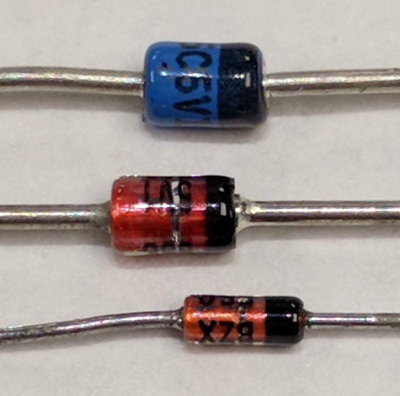
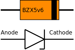
Zener diodes can be identified by the letter "Z" in the name or by having the zener voltage as part of the name. For example a 1N4148 is a regular silicon diode whereas a BZX85c5v6 is a zener diode with a zener voltage of 5.6 volts. In the image of zener diodes the blue and red examples are labelled 5v1 and the smaller orange one is labelled BZX.
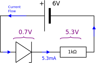
When the anode is connected to the battery positive the zener diode is forward biased and it behaves in the same way as a silicon diode.
The forward bias voltage across the zener diode is 0.7 V and the potential difference across the 1 kΩ resistor is 5.3 V so that a current of 5.3 mA flows in the circuit.
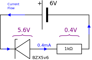
When the cathode is connected to the battery positive the zener diode is reverse biased. The battery voltage is greater than the zener voltage (5.6 V) and so the zener diode conducts. The voltage drop across the zener diode is maintained at 5.6 V and the potential difference across the 1 kΩ resistor is therefore 0.4 V leading to a circuit current of 0.4 mA.
In reverse bias, the power dissipated by the zener diode is 5.6 V × 0.4 mA = 2.2 mW.
The transfer characteristics of a device describe how the current changes as the potential difference changes.
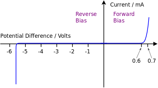
In forward bias the current is initially zero when the potential difference is less than 0.6 V and then the current rapidly increases as the potential difference increases to from 0.6 V to 0.7 V. The forward bias potential difference does not exceed much more than 0.7 V when current flows through the zener diode and therefore the zener diode is used in series with other components.
In reverse bias the current is initially zero when the potential difference is less than the zener voltage. When the potential difference exceeds the zener voltage the current rapidly increases. The reverse bias potential difference across the zener diode is almost constant once current flows and so the zener diode must be used in series with other components.
Note: There must be a few milliamps of current flowing through the zener diode before the reverse bias voltage remains constant as can be seen by the corner on the graph.
In both forward bias and reverse bias the zener diode is a non-ohmic component having a very high resistance when the potential difference is low but reducing to a very low resistance for greater potential differences.
In reverse bias a zener diode acts as a very basic voltage regulator. A variable input voltage will result in a (relatively) constant output voltage.
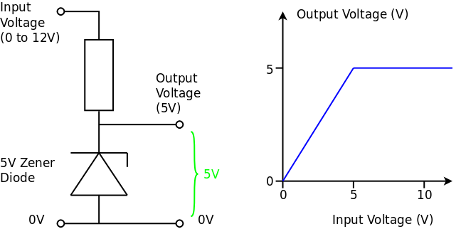
When the potential difference across the zener diode is less than the zener voltage no current flow through the zener diode. Assuming no current flows through the load, the potential difference across the resistor will be zero and the output voltage is the same as the input voltage. If current flows through the load, the output voltage will be less than the input voltage due to the potential difference across the resistor.
When the input voltage is greater than the zener voltage the zener diode conducts in reverse bias, current flows through the resistor to ensure the potential difference across the zener diode remains constant. Therefore the output voltage remains constant even when the input voltage changes.
A zener diode can be used as a reference voltage in a comparator circuit.
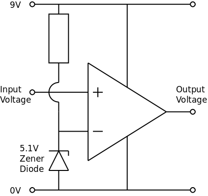 The zener diode in reverse bias and the series resistor provide a fixed voltage at the inverting input of the operational amplifier. In the diagram, this is 5.1 V.
When the input voltage is less than 5.1 V the output of the Op-Amp comparator is approximately 0 V. When the input voltage is greater than 5.1 V the output of the Op-Amp comparator is approximately 9 V.
The advantage of using a zener diode to provide a reference voltage rather than a potential divider or potentiometer is that the reference voltage remains fixed even if the power supply voltage fluctuates. When a potential divider is used to provide a reference voltage, changes in the supply voltage result in changes in the reference voltage.
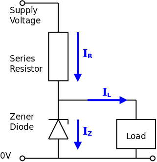
Used in reverse bias, a zener diode always needs a suitable series resistor. The resistor value must be low enough to allow adequate current to flow through the zener diode and the circuit (the load) connected in parallel with the zener diode. The resistor value must be high enough to avoid damaging the zener diode if too much power is dissipated.
 There are two situations to consider:
Situation 1: Knowing the maximum power handling of the zener diode, calculate a suitable value for the series resistor and then calculate the maximum current that can flow through the load.
Situation 2: Knowing what current the load requires, calculate a suitable value for the series resistor and then choose a zener diode with a suitable power rating.
Example 1: A 5.6 V zener diode is rated at 500 mW. What series resistor is needed for use with a 12 V supply? How much current can be provided to the load if the zener diode requires a minimum reverse bias current of 4 mA?
From the diagram it can be seen that current in the resistor = current in zener diode + current in load. The maximum current will flow in the zener diode, and maximum power will be dissipated, when the load is disconnected and takes zero current.
Example 2: A load requires a steady voltage of 5.1 V and a current of 2 A. What value of series resistor must be used if the supply voltage is 12 V and the zener diode requires a reverse bias current of 20 mA? What must be the power rating of the zener diode?
Note: The above example is a very poor way to derive a steady 5 V from a 12 V supply. There are much better methods but the example shows how the calculations should be done.
© Paul Nicholls
April 2019

Electronics Resources by Paul Nicholls is licensed under a Creative Commons Attribution 4.0 International License.